Admin
مدير المنتدى


عدد المساهمات : 18996
التقييم : 35494
تاريخ التسجيل : 01/07/2009
الدولة : مصر
العمل : مدير منتدى هندسة الإنتاج والتصميم الميكانيكى
 |  موضوع: Milling Machines موضوع: Milling Machines  الجمعة 01 أكتوبر 2010, 8:02 pm الجمعة 01 أكتوبر 2010, 8:02 pm | |
| 
IntroductionA milling machine is a machine tool that cuts metal with a multiple-tooth cutting tool calleda milling cutter. The workpiece is fastened to the milling machine table and is fed againstthe revolving milling cutter. The milling cutters can have cutting teeth on the periphery or sidesor both. The cutting teeth can be straight or spiral. Milling machines can be classified under three main headings:..
- General Purpose machines - these are mainly the column and knee type (horizontal & vertical machines)
- High Production types with fixed beds- (horizontal types)
- Special Purpose machines such as duplicating, profiling, rise and fall , rotary table ,planetary and double end types
|
Milling attachments can also be fitted to other machine tools including lathes planing machines and drill bench presses canbe used with milling cutters. Additional Notes Cutting Tool Materials... Cutting Tool Materials.. Cutting Fluids... Cutting Fluids.. Milling CuttersThere are a wide range of milling cutters as illustrated in BS 122-1. these include
- Plain cutters ( most types have straight or helical teeth)
- End mills (taper or parallel shank, slotting or shell)
- Cylindrical side and face slotting,screw slotting
- Single,double and equal angle cutters:
- T-slot, convex, single and double corner rounding cutters
- Metal slitting saws:
- Hollow Mills
|
Typical Milling cutters Tee Slot Milling Cutter 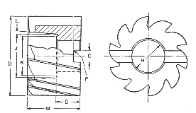 Shell End Mill 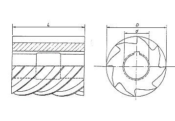 High Helix Cylinderical Cutter  Slotting Cutter Relevant StandardsBS 122-1:1953..Milling cutters. Milling cutters BS 122-4:1980..Milling cutters. Screwed shank end mills and slot drills BS 122-5:1986..Milling cutters. Specification for mounting dimensions and accessories BS 122-6:1995, ISO 240:1994..Milling cutters. Specification for dimensions for interchangeability of cutter arbors and cutter mandrels Column and Knee Machine -Vertical Milling MachineVertical milling machines have their cutting tool spindles vertical and are characterised byby their heavy overarms which are integral with their columns. This provides rigid supportfor the spindle housing which is set at a fixed distance from from the column. The milling head can be adjusted vertically
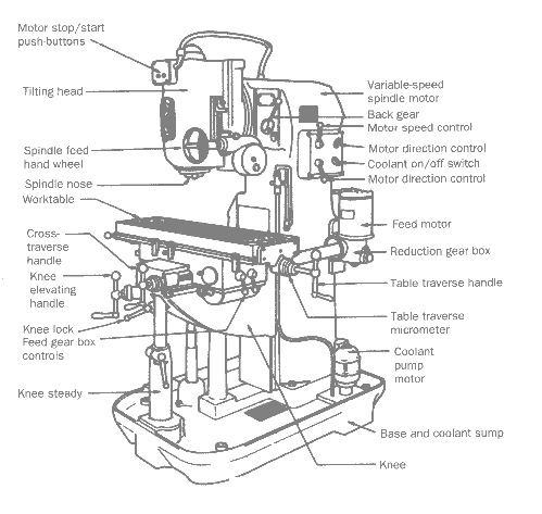 | The diagram below shows the primary controlled motions available with this type of milling machine.
 |
Column and Knee Machine - Horizontal Milling MachineThis is the basic milling machine configuration. The workpiece can be fed in all three axes and is suitable for short production runs but it is not as rigid as a fixed bed machine and should not be used for heavy duty work. Because of the large number of controls it is relatively slow to operate. 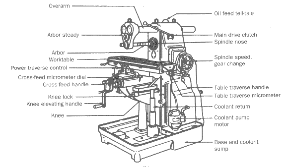 Fixed Bed Milling Machines Fixed Bed Milling MachinesFixed bed or production type machines are designed for rapid metal removal requiring the minimumof operator involvement. On this type of machine the table is fixed permitting machine tablemovement in one horizontal direction only. the workpiece has to be fixed in one locationon the table and all vertical movements for feeds and lateral positioning are by moving the spindle in the spindle carrier mounted on the headstock. A plain machine has just one spindle and a duplex machine has two spindles. this type of machine can have one column or two columns providing more rigidity. 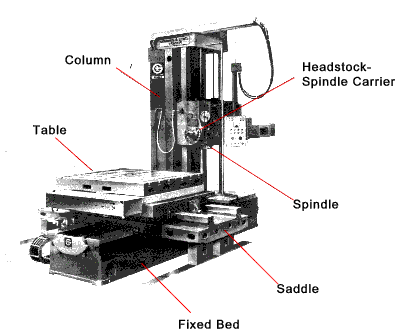 Horizontal Milling Feed Direction Horizontal Milling Feed Direction The direction of feed in relation to the direction of cutter rotation is and important factorin horizontal milling. Conventional up milling requires that the workpiece is fedagainst the rotation of the cutter. In down milling the workpiece moves in the seam directionas the surface of the rotating cutter. The tow alternatives are shown in the figure below 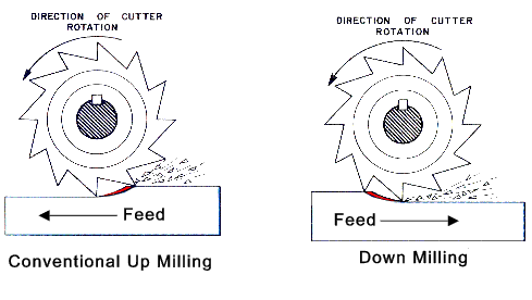 In up milling the cutter tooth starts cutting into clean metal with zero chip thickness and ends with the maximum chip width and rought metal. The cutter stays sharp long and the motion of the feed compensates for wear or backlash in the feed system. The cutter tends to lift up the workpiece and high clamping forces are required. In down milling the cutter tooth starts cutting into the rough metal with a thick chip resulting and ends byproducing a thin chip. The finish is smoother but the forces tend to drag the workpiece along under the cutter. Any looseness in the feed system could result in vibration and chatter with more risk to the cutter. This method is used to produce a good surface finish and for small workpieces that cannot be firmly clamped. Cutting speed HSS cutting tools , RoughingThe table below provides some very approximate cutting speed for different materials using HSS cutterson roughing cuts. For finishing cuts the speeds would increase 20% to 50%. Forcermet (cemented carbide)tipped teeth significantly higher cutting speeds are possible see table below. Surface Speeds
| Material | Rough
Cut | | m/min | | Low Carbon Steel | 24-30 | Med. Carbon Steel
Annealed | 23-30 | High Carbon Steel
Annealed | 18-25 | Tool Steel
Annealed | 18-25 | Stainless Steel
Annealed | 18-25 | | Grey Cast Iron | 18-25 | | Malleable Iron | 25-30 | | Brass | 60-90 | | Bronze | 30-60 | | Aluminium/ Alloys | 120-300 | | Feeds
| Feed per tooth (mm) for HSS and Different Milling Cutter Forms | | Material v | Cutter Type | Plain
Heavy | Plain
light | Face | Side | End | Form | Slitting | Steel Low Carbon.
| 0,25 | 0,15 | 0,3 | 0,15 | 0,15 | 0,1 | 0,08 | | Steel-Low Carbon | 0,2 | 0,13 | 0,25 | 0,13 | 0,13 | 0,08 | 0,08 | | Steel-Med Carbon | 0,2 | 0,13 | 0,23 | 0,13 | 0,1 | 0,08 | 0,05 | Steel-High Carbon
Annealed | 0,1 | 0,08 | 0,15 | 0,08 | 0,05 | 0,05 | 0,05 | Stainless steel
Free cutting | 0,2 | 0,13 | 0,25 | 0,13 | 0,1 | 0,08 | 0,05 | | Stainless steel | 0,1 | 0,08 | 0,15 | 0,1 | 0,05 | 0,05 | 0,05 | | Cast Iron-grey | 0,3 | 0,2 | 0,36 | 0,2 | 0,2 | 0,1 | 0,1 | | Cast Iron-medium | 0,25 | 0,15 | 0,3 | 0,15 | 0,15 | 0,1 | 0,08 | | Cast Iron - Malleable | 0,25 | 0,15 | 0,3 | 0,15 | 0,15 | 0,1 | 0,08 | | Brass /Bronze | 0,25 | 0,2 | 0,33 | 0,2 | 0,15 | 0,1 | 0,08 | | Aluminium/alloys | 0,41 | 0,2 | 0,51 | 0,3 | 0,25 | 0,18 | 0,1 |
| Cermet Surface Speed /Feed RatesThe table below provides some indicative values for the surface speeds and feeds (mm/tooth)that can be achieved using cermet type e.g cemented carbide tipped milling cutters. <> | Material | Surface Speed
(mm/m) | Feed /tooth (mm) | Aluminum
low silicon ( < 8% ) | 450-550 | 0,12-0,18 | Aluminum, Aluminum-bronze
high silicon ( > 8% ) | 250-350 | 0,13-0,2 | | Bronze | 300-330 | 0,13-0,2 | | Cast Iron,Malleable | 120-220 | 0,08-0,15 | | Cast Iron Gray | 180-360 | 0,1-0,4 | | Cast Iron Nodular (ductile) | 180-260 | 0,1-0,2 | | Copper | 370 | 0,18 | | Inconel | 30 | 0,08 | | Stainless steel-Ferr/Mart | 500-800 | 0,05-0,15 | | Stainless steel- cast | 150-250 | 0,08-0,15 | | Stainless steel-304 | 120 | 0,08 | | Stainless steel-316L | 90 | 0,08-0,1 | | Steel, unalloyed | 250-430 | 0,003-0,006 | Steel, low alloy
| 180-360 | 0,08-0,15 | Steel, low alloy
hardened | 120-220 | 0,05-0,15 | Steel, high alloy
annealed | 120-220 | 0,076-0,15 | Steel, high alloy
hardened | 76 | 0,05 | Steel, cast
low alloy | 180-360 | 0,1-0,2 | Steel, cast
high alloy | 120-220 | 0,08-0,15 | | Titanium | 30-64 | 0,05-0,08 | | Tungsten | 120 | 0,05-0,1 |

|
|


