Admin
مدير المنتدى


عدد المساهمات : 18992
التقييم : 35482
تاريخ التسجيل : 01/07/2009
الدولة : مصر
العمل : مدير منتدى هندسة الإنتاج والتصميم الميكانيكى
 |  موضوع: رسالة ماجستير بعنوان Design and Structural Analysis of a Robotic Arm موضوع: رسالة ماجستير بعنوان Design and Structural Analysis of a Robotic Arm  الخميس 20 أكتوبر 2022, 3:09 am الخميس 20 أكتوبر 2022, 3:09 am | |
| 
أخواني في الله
أحضرت لكم
رسالة ماجستير بعنوان
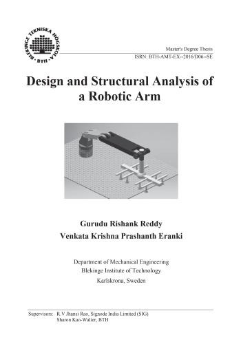
Design and Structural Analysis of a Robotic Arm
Department of Mechanical Engineering
Blekinge Institute of Technology
Karlskrona, Sweden
Gurudu Rishank Reddy
Venkata Krishna Prashanth Eranki

و المحتوى كما يلي :
Contents
1 Notation 7
2 Introduction 9
2.1 Project Statement 10
2.2 Background Study 10
2.3 Research Problem 11
2.4 Scope of Implementation 13
2.5 Objectives 13
2.6 Research Questions 13
2.7 Preliminary Discussion 13
2.7.1 Articulated Arm Robots 14
2.7.2 End Effector of the Robot 15
2.8 Related Works 16
3 Design & Drafting 17
3.1 Mechanical Design 17
3.2 Part 1 19
3.3 Part 2 22
3.4 Part 3 23
3.5 Part 4 & Part 5 24
3.6 Pneumatic Cylinders 26
3.7 Assembly 27
3.7.1 Joint 1 (Waist & Shoulder) 27
3.7.2 Joint 2 30
3.7.3 Joint 3 (Elbow) 31
3.7.4 Joint 4 (Wrist) 32
3.7.5 Joint 5 (End Effector) 33
3.8 Dynamic Behaviour of Robotic Arm 35
4 Materials 42
5 Simulation & Analysis 45
5.1 Need for Stress Analysis 45
5.2 Loads & Boundary Conditions 46
5.3 Export to FEA Module 48
5.4 Meshing 51
5.5 Stress Analysis Environment 524
6 Analytical Model 54
7 Results & Discussions 57
7.1 Stress Analysis Results 57
7.2 Convergence 68
7.3 Fatigue Analysis 70
7.4 Stress-Cycle (S-N Diagram) 76
8 Summary &Conclusions 78
8.1 Validation 78
8.2 Conclusion 80
8.3 Future Works 82
References 83
Appendix 84
Link to the Motion Demonstration of the Robotic Arm 84
A. External Forces Acting on Parts 84
B. Deformations on Parts 87
C. Moment Vs Time Graphs 90
D. The Factor of Safety on Parts 92
E. Von-Misses Stress of Part 5 with CFRP material 94
F. Matlab Code for calculating the Number of Cycles 955
List of Figures
Figure 2.3.1: The Prototype of robotic arm (Pick and Place Operator) 12
Figure 3.2.1: The upper part of Oldham Coupling. . 20
Figure 3.2.2: The shaft and Key of Oldham Coupling. 21
Figure 3.3.1: The CAD design of Part 2 . 23
Figure 3.4.1: The CAD design of Part 3 . 24
Figure 3.5.1: The CAD design of Part 4 and Part 5. . 25
Figure 3.6.1: The CAD design of pneumatic Cylinder. 26
Figure 3.7.1: The CAD design of Joint 1 (Waist and Shoulder) . 28
Figure 3.7.2: The CAD design of Joint 2 31
Figure 3.7.3: The CAD design of Joint 3 (Elbow) 32
Figure 3.7.4: The CAD design Joint 4 (Wrist) 33
Figure 3.7.5: The CAD design of Joint 5 (End Effector) 34
Figure 3.7.6:The Complete Assembly of Articulated Arm Robot. 35
Figure 3.8.1:The dynamic behaviour of Pneumatic Cylinder. . 36
Figure 3.8.2: The Prototype of Robotic Arm in three sections . 37
Figure 3.8.3: The Top view of Robotic Arm. 38
Figure 3.8.4: The Graph between Position vs Time. 39
Figure 3.8.5: The flow chart construction of Robotic Arm . 40
Figure 3.8.6: The Graph between Position vs speed 41
Figure 3.8.1: The Graph between Strength and Density of the Material. 42
Figure 3.8.2: The Graph between Strength and Relative cost per unit volume.
. 43
Figure 3.8.3:Part-5 assigned with CFRP material. . 446
Figure 5.2.1: The Force acting on the sheet . 47
Figure 0.1: The Export to FEA. 48
Figure 0.2: The Part-5 in Export to FEA. 50
Figure 0.3: The Output Grapher and Time Series 50
Figure 5.4.1: The Joint were the meshing is excited 52
Figure 5.4.2: The Meshed Part of FEA. . 52
Figure 7.1.1: The graph between Time (sec) vs Stress of Part 1 59
Figure 7.1.2: The graphs between Time (sec) vs force and moment. . 60
Figure 7.1.3: The stress distribution plot of Part 1. . 61
Figure 7.1.4: The Stress distribution of Part 2 . 62
Figure 7.1.5: The Stress distribution of Part 3 63
Figure 7.1.6: The Stress distribution of Part 4 . 64
Figure 7.1.7: The Stress distribution of Part 5. 65
Figure 7.1.8: The FOS of Part 5. 67
Figure 7.2.1: Convergence Plot for Part 2 ……………………………….….69
Figure 2.1.1: Aluminium 6061 Fatigue Data from Experiments ………….72
Figure 7.3.2: The graph between Number of Cycles(N) vs Stress (Pa) 77
Figure 8.1.1: The Factor of Safety for Part 2 . 79
Figure 8.2.1: The position of Shearing Machine in Industry. 817
1 Notation
A Area
B Width
D Diameter of Solid Shaft
E Young’s Modulus
H Height
I Moment of Inertia
L Length
M Mass
Q Weight
R Radial Arm
r Radius of Solid Shaft
t Torque acting on Solid Shaft
T Thickness
V Volume
W Load acting on Solid Shaft
࣋Density8
Abbreviations
CAD Computer Aided Design
CFRP Carbon Fibre Reinforced Plastic
DOF Degrees of Freedom
FANUC Fuji Automated Numerical Control
FEA Finite Element Method
FOS Factor of Safety
KSI Kilo pound per Square Inch
SIG Signode India Limited
RCC Remote Censor Control
كلمة سر فك الضغط : books-world.net
The Unzip Password : books-world.net
أتمنى أن تستفيدوا من محتوى الموضوع وأن ينال إعجابكم
رابط من موقع عالم الكتب لتنزيل رسالة ماجستير بعنوان Design and Structural Analysis of a Robotic Arm
رابط مباشر لتنزيل رسالة ماجستير بعنوان Design and Structural Analysis of a Robotic Arm 
|
|


